
Object modes tool-palette
Updated 05 Apr 2018
- QuArK Information Base
- 1. Introduction to QuArK
- 1.5. Model-editor in QuArK
- 1.5.6. Tool-palettes
|
|
Object modes tool-palette
Updated 05 Apr 2018
|
Upper levels: - QuArK Information Base - 1. Introduction to QuArK - 1.5. Model-editor in QuArK - 1.5.6. Tool-palettes |
|
1.5.6.5. Object modes tool-palette |
[ - - ] |
|
|
Index |
|
|
|
Overview |
cdunde - 05 Apr 2018 | [ Top ] |
|
|
Object Dialog Input |
cdunde - 05 Apr 2018 | [ Top ] |
|
Not all objects will use the same
dialog input box.
Which ever object button is active at the time this button is clicked, will produce that
objects dialog input box. If a particular object has its own dialog then that objects name will appear in the title.
Other wise the standard
Object Distortion Dialog will be used for all other objects. |
|
Deactivation |
cdunde - 05 Apr 2018 | [ Top ] |
|
To reactivate it simply click on any of the 'Quick Object Maker' shapes you wish to use. |
|
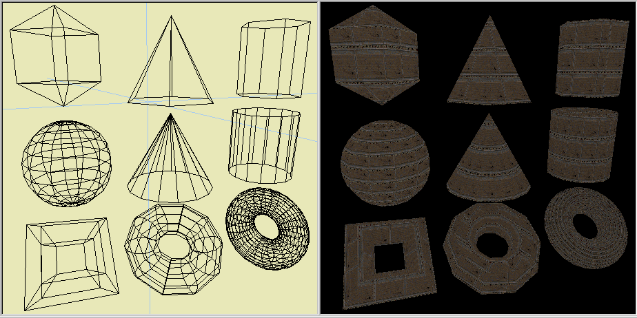
Sphere |
cdunde - 05 Apr 2018 | [ Top ] |
|
Move the mouse forward to add more faces, backwards for fewer faces, right to make it larger and left to make
it smaller. Because the Sphere object is a far more complicated item to compute, creating it will take longer then the other objects as the number of faces it is given increases. Although it can 'freeze' the program for a period of time for processing, it will return the object and become active again. Increasing the amount of its
Object Distortion Dialog
will increase its height, making it more elongated. |
|
Pyramid\Cone |
cdunde - 05 Apr 2018 | [ Top ] |
|
The more sides that are added the more it becomes a cone shape. Once the object has been created you might have to use the special vertex movement function to stretch or reduce its size by dragging its top point common vertex. To use this function simply hold down the ' n ' HotKey when you select, drag and release the LMB. For some reason, you only need to do this the first time the common vertex is dragged. Afterwards the vertex can be moved correctly, without using the special function, in the normal manner of just holding the cursor over the vertex, pressing the LMB and dragging it. Using the special function above without actually dragging the vertex will also create the same results. Increasing the amount of its
Object Distortion Dialog
will increase its height. |
|
Double-Cone |
cdunde - 05 Apr 2018 | [ Top ] |
|
The more sides that are added the more it becomes a double-cone shape. Increasing the amount of its
Object Distortion Dialog
will increase its height. |
|
Cylinder |
cdunde - 05 Apr 2018 | [ Top ] |
|
This can make angled sides or a more curved style cylinder by adding more faces. Increasing the amount of its
Object Distortion Dialog
will increase its height. |
|
Dome |
cdunde - 05 Apr 2018 | [ Top ] |
|
Move the mouse forward to add more faces, backwards for fewer faces, right to make it larger and left to make
it smaller. The amount of its
Object Distortion Dialog
will be the number of sections to create the top, dome, curved part. |
|
Fan |
cdunde - 05 Apr 2018 | [ Top ] |
|
Move the mouse forward to add more faces, backwards for fewer faces, right to make it larger and left to
make it smaller. Increasing the amount of its Object Distortion Dialog will increase its height. |
|
Torus |
cdunde - 05 Apr 2018 | [ Top ] |
|
Move the mouse forward to add more faces, backwards for fewer faces, right to make it larger and left to make
it smaller. This particular object maker has its own Dialog Input Box because of the many different shapes that can be obtained when using a torus object. |
|
Dialog boxes |
cdunde - 05 Apr 2018 | [ Top ] |
|
At this time there are two dialog input boxes
for the QuArK Quick Object Makers Toolbar that are linked
to the Object Dialog Input button.
|
|
Visual Aids & Misc. Info |
cdunde - 05 Apr 2018 | [ Top ] |
|
|
Copyright (c) 2022, GNU General Public License by The QuArK (Quake Army Knife) Community - https://quark.sourceforge.io/ |
[ - Top - ] |

 Pressing this button, will open a dialog input box for the
 Deactivator button: To return to regular operation mode you must click this button to turn 'Off' the 'Quick Object Maker'.
 Quick sphere maker: After you click this button, you can draw spheres in the editor with the left
mouse button and each sphere will be turned into an actual model object.
Quick sphere maker: After you click this button, you can draw spheres in the editor with the left
mouse button and each sphere will be turned into an actual model object. Quick pyramid-cone maker: After you click this button, you can draw pyramids-cones in the editor
with the
Quick pyramid-cone maker: After you click this button, you can draw pyramids-cones in the editor
with the  Quick double-cone maker: After you click this button, you can draw double-cones in the editor
with the
Quick double-cone maker: After you click this button, you can draw double-cones in the editor
with the  Quick cylinder maker: Clicking this button allows you to draw cylinders in the editor with the
left mouse button and each cylinder will be turned into an actual model object.
Quick cylinder maker: Clicking this button allows you to draw cylinders in the editor with the
left mouse button and each cylinder will be turned into an actual model object. Quick dome maker: Clicking this button allows you to draw domes in the editor with the
  Quick fan maker: Clicking this button allows you to draw fans in the editor with the left
mouse button and each fan will be turned into an actual model object.
Quick fan maker: Clicking this button allows you to draw fans in the editor with the left
mouse button and each fan will be turned into an actual model object. Quick torus maker: After you click this button, you can draw a torus in the editor with
the left mouse button and each torus will be turned into an actual model object.
Quick torus maker: After you click this button, you can draw a torus in the editor with
the left mouse button and each torus will be turned into an actual model object.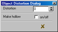 Object Distortion Dialog: This is a basic dialog input box that is used by every object maker on the
toolbar unless a specific one has been created for that particular object maker.
Object Distortion Dialog: This is a basic dialog input box that is used by every object maker on the
toolbar unless a specific one has been created for that particular object maker.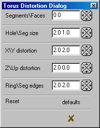 Torus Distortion Dialog: This is a custom dialog input box that only relates to and effects the torus
object maker. The basic dialog box, covered above, has no effect on the torus object. Many shapes can be created from
a torus using one or more of these input items.
Torus Distortion Dialog: This is a custom dialog input box that only relates to and effects the torus
object maker. The basic dialog box, covered above, has no effect on the torus object. Many shapes can be created from
a torus using one or more of these input items.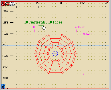 Ruler guide in 2D views: This function has been incorporated to show dimensions as a drag is taking place
and upon its completion as well. The 'Rulers' are fully dependent on their normal
Ruler guide in 2D views: This function has been incorporated to show dimensions as a drag is taking place
and upon its completion as well. The 'Rulers' are fully dependent on their normal